fredag 19. desember 2014

Happy Holidays!

Just a little rendered pic with structural framing and columns based on the Dynamo Text node by Ian Keough!

(I'm not even remotly touching the upload button for a pic of the Dynamo definition for this. It is one hairy definition..
To give you an idea:

torsdag 18. desember 2014

Practical Dynamo: Embedded rock bolts and coordinates to excel

Some colleagues of mine at the company I work for had a very interesting project with a treatment plant for wastewater inside a mountainhall recently. They had a quite interesting workflow using Civil 3D for the rock excavation and Revit for modelling the internal infrastructure.
However they came across a challenge when the contractor requested coordinates for all the rock bolts in the project. And not only the starting point but also the point where the bolt would enter the rock surface.
The challenge ended up out of house and was solved by a third party developer. I do not know how much time they needed and for what cost, but what I know is that if the problem would have come across now, it could have been solved using Dynamo.

"But of course you would." freely after James Bond

The following version was up and running in about three hours and should do the job quite well. It utilizes a generic face based family with an extruded solid and a length parameter. In addition to the extruded solid it is important that the family include a model line which have the same constraints as the solid. This is because we want the direction the face based family is pointing in dynamo.

I've also added the ability to extend the rock bolts to the rock surface with an embedded depth.

RMBD: (Revit Model Before Dynamo..)
First half of the script:


Second half:


RMEDAD: (Revit Model, Excel and Dynamo After Dynamo..)


And a little Screencast in poor english as usual! :)


PS! If you're in dire need of christmas spirit and you haven't heard it yet, here is some top level music for ya'll: White Christmas from the awesome Ben Goh.


Happy holidays, everybody!

fredag 5. desember 2014

Randomized trees by area in Revit

Today I'm going to show you a workflow for generating a number of randomly placed trees inside an area in Revit.

Once again I utilize the topo to surface conversions which I've shown you before.

The workflow:
1. Draw a closed area with model lines. (Must be higher than the topo)
2. Select the model lines in Dynamo
3. Select the topo in Dynamo
4. Set the number slider according to your taste for tree quantities..
5. Run!

The definition looks like this:

Inside Revit after placement:


And a little screencast video as usual: Screencast

mandag 1. desember 2014

Hardscape on Topography: The ancient Revit problem

So I'm not at all envious at the guys at AU 2014 hacking away at Dynamo. Or maybe a little.. Maybe even a little too much.. But what can a man do?
Well, he can hack away at Dynamo anyway.

This time I will give the age old problem with hardscape following topo a go.. Or is it a problem??

Just the other day I discovered Marcello Sgambelluris post about how to get a hardscape elements to follow a topo: The Revit Complex and the AU session about the same thing (google it!). 
I found it very interesting, and it's a beautiful workaround solution using dwg export and import to get a wall to follow a topo.

Quite inpired  by the post, with Dynamo being all it is and my recent post about piles in mind, I felt that it had to be some other way using Dynamo.

For this post I focused on a fenceline. 

What I ended up with was a solution where you model your fence line with model line elements, each as long as between two posts, using a two-point adaptive family as the fence family and then with some Dynamo magic (Not to be confused with the illusionist) you get a fenceline following your topo.

the family in use here is just a fence "rig" and you could always make a more detailed family, but I think it shows the trick! :)

Before, with Site plan, 3d-view and two-point fence family
The script
Codeblock version

so with the topo and model lines selected we get this:

After

and here is a little screencast for you all: (CAUTION! Bad english, bad mic and nasal accent.. ;) )

onsdag 26. november 2014

Last post about topos and piles forever.. Hopefully..

EDIT: I've edited this post to reflect some changes done to my original script and that units handling in Dynamo has changed (for the better.) The script is way easier now. Among other things I recommend using the topography handling provided in the spring nodes package.

Here is the light version of the script. Selecting the piles in question is a matter of choice. I went for the simplest in the example.


2000 piles extended in less than one minute! :)


onsdag 19. november 2014

Window tag with top/bottom elevation

For quite a few years we've had an ongoing discussion (among structural engineers) about how to best get the top and bottom of openings for windows, doors etc. out on a floor plan in Revit. I think the common ground has been to just enter text, or do a workaround with a spot elevation.

This is time consuming and bound for mishaps when we coordinate a project in 3d, but produce 2d drawings for the contractor where we override the information in the 3d model with text or maybe also a misplaced spot elevation. 

The following workflow probably is one of many solutions, and probably not the best either. I know that there are many ways to put a hole in a wall, each method with its own perks and flaws.
I'm going to use an "empty" window family to produce my openings, but I'm guessing the dynamo definition could be used for other openings as well.

Here is the definition:


(The GetTypeParameter.FrmFamilyInstance is a package found on the package manager and I think it's made by Peter Kompolschek.)

Before using this definition I have made two shared parameters called "Top window" and "Bottom window" which I imported into both the project parameters and the window tag.

Results:

If someone have a better idea for this, then let me know!

Here's a screencast video for the above. (and you have to excuse my overly affectionate mouse waving.. Jeezz..)

mandag 17. november 2014

Extend pile length to topo: It's working!

And it involves not one definition, but two!! So that's a letdown, I know.. But on the bright side I used a staggering 2 minutes with the following workflow to get all the piles in my project extended to a topo... So if you have many straight piles and want to use dynamo, read on.

It is however a kind of a workaround so I included a video in the end to show the workflow, as it is not simple as click-tada!

I must admit that my mind has pondered this problem for some time now. Not being able to solve it (effectively) by any standard means, it was one of the reasons I got interested in dynamo.

I've come to learn that a lot of people have solved this before, by using a class in the Revit API called ReferenceIntersector and it is probably still the best way to solve it. Partly because I think it would use less resources and partly because it is vector driven and therefore able to handle angeled piles with slope.
But since I'm still not a programmer I leave it up to one of you clever readers with programming experience to solve that. What I do is workarounds, and I love it when it works!

First I tried fiddling around in dynamo with the Point.Project node, but as I said in an earlier post, that fell to the ground quickly as the node couldn't read a mesh derived from a topo. (Colin McCrone said they're looking into mesh handling as we speak, though! Nice!)

Then I tried the Intersector way, but that involved heavy programming, so that fell through..

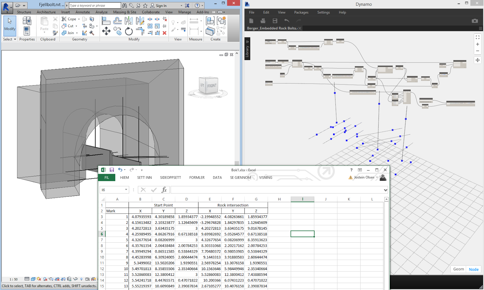
So I thought long about this and it kept getting back to the same question: How do I get the Z-value from a topo when I have the X and Y coords defined?
But then it struck me. What is the easiest way to place something on a topo??

A site component, of course!!

What if I make a small site component, place it with XY-coords and it just automatically snaps to topo? then I could just get the location of top pile and top site component, a simple subtraction and then voila?

Once again it involved programming, and I thought I got very far. But I couldn't get it to work, so I gave up and asked on the forum. And I'll be damned if the forum didn't deliver! Or Andreas Dieckmann to be exact. He didn't just point me in the right direction, he didn't just give me the modified python script on a copy/paste basis but he even annotated it so I could learn what the different parts was for. I'm nearly speechless! Huge thanks, Andreas!

The workflow goes like this:
1. Use the first graph to place site elements by level.
2. Pick all the site elements and pick topo as new host and set offset to 0 in Revit.
3. Open second graph and select both piles and site components
4. Press run, and delete the site objects if you don't want them

First definition:

Second definition:

How you select elements can of course be edited, I just like the manual way! ;)


So that works while I wait for someone posting a more beatiful solution for this problem with angeled piles and all! And I guess you could use it for placing things on a topo as well. Trees and what not..

onsdag 12. november 2014

Auto section box - Dynamo style

For a while now the COINS Auto-section Box app has been one of the most downloaded apps on Autodesk Exchange. It's a app for aligning a section box with selected elements in a 3d-view with or without an offset and I know many people think it's awesome. As do I.

Look it up here: Autodesk Exchange - COINS auto-section box

If you however, like me, would be interested in a less user friendly version in dynamo, read on..

The only real reason for doing this in dynamo is that: you can!
And I'm not going to bother you for too long before showing you the goodies, but I would just like to point out one thing:

I'm not a programmer!

And I think therein is the deepest beauty of Dynamo!

The people actually designing stuff, the engineers, architects etc. can get an idea for some sort of tool or automated task, and then be able to create their own tools for obtaining that. How liberating isn't that for the industry? And it's free too!

However, for the following example it's not an original idea, nor is it doable without programming. But the people on the dynamo forum is really helpful. And many times one can copy things directly from examples etc. Do it a couple of times and you get the idea!

That said I would like to especially thank Dimitar Venkov for helping me out with the Python side of this definition.

nuff said...

Here is the .dyf file with the python script:


The basic workflow ,before the Python script, is that dynamo obtains the bounding boxes from the elements we've selected and we sort out the min/max values to get the cornerpoints. In addition I've included a offset input.
(The nodes Cuboid.ByCorners and BoundingBox.Bygeometry can be replaced in the 0.7.3 version with the node BoundingBox.ByCorners, but I had to roll back my version to 0.7.2 due to some issues with 0.7.3.)

I'm not sure I can fully explain the python script and I would probably be bullied by the real programmers. But the basics are that everything above the middle is required to use the Revit API, and the actual code is setting a bounding box by the cornerpoints of the dynamo bounding box and setting the view spesific sectionbox equal to this bounding box. That was a lot of bounding box...

In revit before and during selection:
In revit after, with the dynamo definition:


The -dyf file is already released in the package manager, be sure to take a look. And if anyone of you reading this is a programmer, be sure to let me know if this can be done easier! :)

lørdag 8. november 2014

Extend pile length to topo, almost...

Soooo, this problem have circulated for some time, and most probably somebody have solved it. But I haven't seen anyone solve it elegantly yet. Alas, neither shall I..

The situation:
- I have a pile family, in this case an adaptive one set with a standard length.
- I have a topo that represents the bedrock based on contractors data
- I want the piles to magically attach to topo.

Is this really to much too ask?

Well, it seems to be. The issue is in the Point.Project node in dynamo which won't take a topography for a geometry. Stupid node.. (Or stupid me for not understanding what to put in the node..)

This is basically how i wanted the definition to look like:


And this is what I ended up with:


And here you can clearly see, as my teacher used to say when one couldn't see nothing clearly, that the definition only works when the topography consists of nothing but closable polycurves.. not good enough.

So this post is really a plea for getting topography or a mesh derived from topography to work in the Point.Project node. Pretty please, almighty programmers?

However, when the topo does consists of closable polycurves it works pretty good. I've tried with 115 piles and you can see the response time here:


If someone have solved this in dynamo, I'll pay you with one bottle worth of local beer sent by mail for the solution.

onsdag 29. oktober 2014

Definitions in code blocks for dummies

Up to this point I've not realized the possibilities of using definitions in codeblocks. However, it can be quite useful!
In an earlier post I showed you a definition that read textfile based coordinates into Revit:

However, it's tedious to repeat the large codeblock over and over, and though I haven't figured out how to repeat the operation automatically based on list length, I've managed to make a definition in a code block that, when called, can be repeated more easily:


So I will try to explain what parts make up a callable defintion. (By callable I mean a seperate standing code block that we can "call" from another codeblock.)


Red= by typing "def" you tell dynamo that this codeblock will be a callable codeblock
Blue= This is the name that you later will call from another code block.
Green= Green contains all the outer variables that will have to be inputted to execute the definition (The left side of dynamo nodes)
Orange= this is the name of the variable.
Yellow= The colon means that whatever follows will define what kind of variable the "list"-variable will be.
Cyan= this defines the variable "list", in this case "var[][]" means a "list of lists of variables"
Pink= In a code block definition "return" is the output of the definition and must be included
Purple= "{" marks the start of the definition and "}" marks the end

If you want multiple variables you seperate them by commas inside the parentheses

The rest is the "body", that would be the calculations and stuff that will be executed based on the inputs.

So when I call this node in an ordinary code block I would type: Curvebyind(x). (Notice that I don't have to use "list" as i did in the definition)

A variable can be many things but I've listed some of them here, including an error that comes if you put a floating number(3.145) into a function that expects an integer:

PS: If this is way below your level of dynamo expertise, I've left something out or ,even worse, written something entirely wrong, then I hope you get provoked enough to supplement in the comments! :)

onsdag 8. oktober 2014

Text based coordinate files and how to import them to Revit

In Norway we have a format for coordinates that is used by surveyors, consultants and others alike. It has the file extension .kof and I do not think it's very widespread outside our fiordinfested country

Basically this is a text format which have seperators for substrings or subvalues. Like this:
In the example over, 09_91 marks start of a line and 09_99 marks end of line.
then:
Coordinate block (05) - point number (1037) - Theme code(2201) -Xvalue - Yvalue -Zvalue

By doing some prep work before putting this into dynamo, one could take this via excel and importing into dynamo that way, but where is the fun in that?

With some intense googling, cursing and doing other hair loosening activities I found the keys to my problem: Python and the commands re.compile, find.all and DO NOT forget re.dotall*

However, the problem was to find, extract and divide ALL substrings between 09_91 and 09_99, not just the first and last or every nth item.

So here is the syntax:

And that produces this:


Which means we have separated out each specific string between 09_91 and 09_99.
(I guess I could have done this with inputs for other seperators as well rather than writing it as string directly in the code.)
Not entirely sure I've figured out the best way to go from here, but depending on the string structure one could compose a function like this:


From here on I'm not sure what to do. The goal have to be minimum input by others who will use this definition, and in this workflow one would have to duplicate the steps in the first codeblock pr list instance between 09_91 and 09_99. This is very tedious for large coordinatefiles. Hopefully someone have the solution for a more iterative method! :)

As per now it serves the purpose, but it will have to be polished to work as it should.

If anyone have tips or comments on how to solve the iterative part, please do not hesitate to contact me! :)


*re.DOTALL makes the find.all function find all string characters between 09_91 and 09_99 INCLUDING those on new lines in the string, without it: No results but a empty list...

torsdag 2. oktober 2014

Preview dynamo and bridges

Playing around in Revit with divided lines, adaptive profiles and dynamo. What a tool box! Hope to be able to share something more soon:


torsdag 18. september 2014

Revit+Aspose+QR-codes+Dynamo = Gamechanger

Well, I'll tell you this much: Dynamo seriously impress me on a daily basis..
So the story goes like this:

Was looking around the internets, searching google for cool libraries to use with Ironpython, which is the implemented version of Python in Dynamo. I figure out as I'm fooling around that the positive side with Ironpython is that you can also call .NET code directly. Ok.. what is actually .NET code , you say? I don't know.. actually.. So naturally I search for:

"Cool .NET libraries" And somewhere in my googling i found this site: http://www.aspose.com/.net/total-component.aspx

As I scroll down I see that they have a " Apose.Barcode for .NET"-component
That would be a Barcode tool for .NET applications


So I thought: wouldn't it be cool if I could generate QR-codes for Revit elements and one could use it for whatever? Marking columns, register whether the column has arrived at site or not, get QR-codes off the drawing and check whatever..

So I thought that I'll someday read into this and learn myself how to access .NET libraries from Ironpython from within Dynamo.... Tedious at best for a non programmer..

But none the less I downloaded the free trial from Aspose, and I saw that it was a .dll file. (Dynamic Link Library) and it struck me:


Isn't dynamo supposed to read DLL-files directly??

Oh yeah it is:

And it just shows up like this:
It got AustraliaPostFormatControlCode for crying out loud!!! Don't ask..

So 4 walls, some marks, comments and an hour later this is the result:


and also: The image files can be loaded into schedules and onto sheets! :)


Enlarged version:


I can't even begin to think of the possibilities this opens up for. Does anyone know similar systems that can be used with Revit in the same way?

mandag 1. september 2014

List.FilterByBooleanMask and Boundingbox

This week I would like to look deeper into a earlier post where I described the List.Filter and List.Map functions. http://jbdynamo.blogspot.no/2014/08/listfilter-og-listmap.html  (In Norwegian)

One of the things I mentioned in that post was to have the possibility of checking whether a point is within a bounding box or not.

So here it is:


The nodes in the upper part of the definition are the bounding box workflow. The bounding box is a simple geometry defined by cornerpoints, but can possibly be rooms or any other kind of geometry.

In the bottom you can see a similar workflow for extracting a list of points that are within two Y-values.
(Notice the &&-operator that means that both conditions must be met to be true in filter list.)

So as you can see the List.FilterByBooleanMask is a quite powerful node!

onsdag 20. august 2014

torsdag 14. august 2014

Detail numbering, callouts and dynamo. (And changing to english..)

Ok, so I am not perfectly fluent in english, but I will try the best I can from here on.

The reason for changing to english is of course enabling others to read my blog as well as the norwegian vikings.
So here goes..

I don't know the best workflow for giving names and numbers to callouts in Revit. It has been up for discussion over the years and we've landed a sort of "manual labor" way of doing it.

Something like this:

1. Create callout
2. Name the callout manually with a prefix and a serial number. For instance "HD 1", (Horizontal Detail number 1)
3. Put callout on sheet. Callout gets a detail number (which is sheet specific)
4. Manually update the detail number to match the view name...
5. Tada.. View name and detail number now match.


However, this is tedious and uncomfortably timeconsuming, especially on larger projects.

so without changing to much of the workflow, what can we use to automate a little bit?..

Well, dynamo of course:

Here's step 2 in the workflow automated to change all views containing "Callout" (Which is default naming convention i Revit) One problem I haven't figured out yet is how to run this multiple times when adding callouts and get the definitions to start from the last generated number. Let me know if you have suggestions!


For various reasons I have chosen to split step 2 and 4, but I think they could be in the same definition without problem.

So step 4: Here I have a definition that use many of the same nodes as the one in step nr 2(I tried making it a custom node, but then it crashed dynamo hard..), but this one gets all the view names and writes it to the detail number parameter. Keep in mind that you must place the callouts on sheet before doing this.


So now we've at least automated it a bit.

However I got this feeling that others out there have better workflows even without dynamo, so don't be shy and share if you care! :)


List.Filter og List.Map

Har drevet litt videre med listebehandling i Dynamo og selv om det er laaaangt igjen til zen iht. denne tabellen Six phases of Revit  så er jeg kanskje på nivå 2-3.

Har tenkt til å forklare to funksjoner idag som har med listebehandling å gjøre.

1. List.Map

List.Map er en funksjon som lar deg "mappe" en funksjon over en liste og bevare listestrukturen din.
Under har jeg laget en enkel liste med stringinputs. Jeg vil finne ut om noen av listeverdiene inneholder stringverdien "xyz".

Map funksjonen lar meg altså bruke String.Contains noden uten å ha en string input i selve String.Contains noden. Ikke helt enkelt, men lettere å se på bildet tror jeg.


Jeg sitter altså igjen med en liste med true/false-verdier og de er ikke så mye verdt i seg selv.
(dette er et eksempel, men for String.Contains noden kan man kjøre listen rett i noden og få samme resultat som ved å mappe den)

Men, vi kan bruke..

2. List.FilterByBooleanMask

Som lar oss bruke true/false-listen vi akkurat har laget til å filtrere den originale listen. 


Kan hende andre har bruksområder jeg ikke kommer på, men kan feks brukes til å filtrere ut punkt verdier som har en gitt x verdi, sjekke om punktverdier er innenfor en gitt verdi osv

Snakkes.


mandag 11. august 2014

CSV import fra web

I Dynamo finnes det bare en node for å lese fra en .csv fil (comma seperated values). Hvis man har lyst til å lese inn en csv fil fra en webside får man kun en lang string fil å forholde seg til. Dynamo har riktignok gode muligheter for å behandle strings, men det hadde vært bedre å få csv til en tabell/list direkte. 

Si vi skal ha tak i folkemengde pr år i rådata fra ssb under


Ved import via vanlige noder må man benytte mange stringbehandlinger for å få det man vil ha:


Synes da denne under er enklere.


customnoden her er ikke lagt ut enda, men den ser slik ut, med stor takk til Maciej Wypych for hjelp med Python programmeringen! Her importerer vi altså en csv-reader som ligger i Ironpython mappa og skriver data til en liste. Har ikke programmeringsbakgrunn whatsoever, men med litt lesing om Python, god hjelp og noe å kopiere fra er man langt på vei!


Og til sist begge samlet hvor man ser at vi har fått tak i folketall pr år på to forskjellige måter. Jeg foretrekker den øverste.


Snakkas..