søndag 13. mars 2016

Ammo: Creating Isovists in Revit


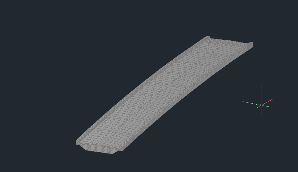
I've been inspired lately by raytracing and what you can use it for in an Revit/Dynamo environment. The inspiration came from Twitter and the wonderful expertise the people I follow possess. It started with Dieter Vermeulens tweet and blogpost here. From there I tested a quick example by using some of the same logic in a topography environment in Revit, ended up looking like this:

(Just to let you know, the raytracing functionality in revit can't do topos, but it can use family instances generated with spring nodes. Hint hint..)

Anyway, I shared the above pic on Twitter and it got retweeted by, among others, "some guy" called Amar Hanspal. I may have to study the Autodesk Organization Chart a little better, because it was Dieter who had to point out that it was Autodesk' very own Product SVP . Holy cow.. Thanks!

Now another helpful guy called Dimitar Venkov, pointed me in direction of another wise gentleman called Kean Walmsley and his blogpost here.
Reading this post I got to know what isovists are, and naturally wanted to explore this a bit more. 

From Wikipedia: "A single isovist is the volume of space visible from a given point in space, together with a specification of the location of that point."

and a more graphical explanation of a 2d isovist because we are so visually oriented..

Dieter confided to rooms and I thought why not go outside that window and into the cityscape? In a preliminary design phase it would be nice to have some sort of analysis of what you actually see from the 73th floor balcony in your building wouldn't it?

So how do we get about this then? Well, the guys behind the acoustamo package have pointed out that the raytracing in Revit is a bottleneck. But I think it has worked pretty well so far. Another simplification I've made is that I have enclosed the entire test area with a circular wall that I've hidden in all but one view
to complete the isovist inside those walls. Could have been handled by importing all the geometry to Dynamo and creating some sort of enclosing geometry there, but I think it will suffice for all intents and purposes.

Overview:

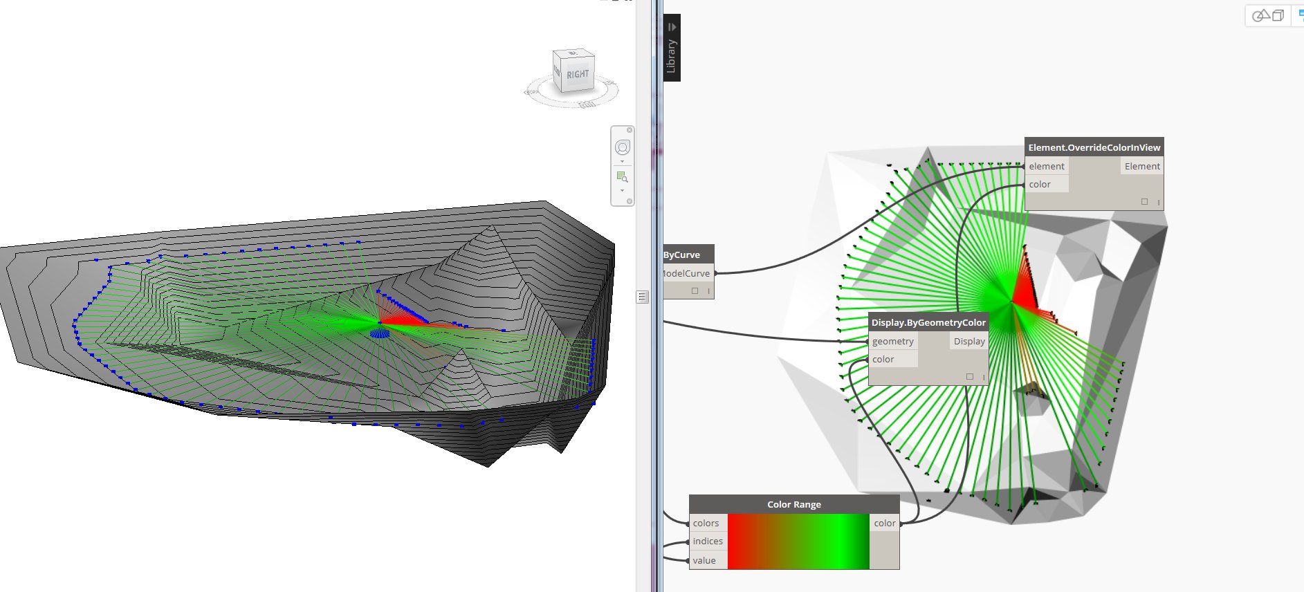
Raytracing and filtering:
(There are many way to produce the vectors which are fed into the RayBounce node, but i used spherical coordinates as it is applicable to 3d isovists as well.)

Line based result options:

Polycurve/patch based result options:

As this is more of a proof of concept I've included some different result presentations as examples. Let's hope some real architects come up with something better. (They're probably using grasshopper/rhino anyways, but still..)

Results from the various parts:

Regular detaillines:


Model curves overridden by color by lengths:
Visualisation in dynamo:


Model curves by perimeter:

Detail region created from the above model curves:


Direct shape by perimeter:


Now, there are many things you can use this for and the pics above are but a few examples. Still, the power of Dynamo is that it makes us able to create tools where WE can decide what the outcome will be by ourselves. 

Now if I only can figure out a way to create a 3d Isovist solid..


onsdag 9. mars 2016

Reinventing the Wheel: 3D DWG to Revit Family Instance

It has been possible for as long I've used Revit to import 3D-DWGs. Who haven't wondered why all of my DWG geometry is visible though my section has like 5 mm far clip offset?? (Hint: All elements in Revit needs a category..)
And if that didn't work maybe we tried exporting to SAT and import it in Revit. Pretty decent, but sometimes the geometry went curly when the coordinates were to high numbered.


I've also found myself using the 3D-DWG as reference and try to remodel the entire thing in Revit. But this is at best time consuming, and at worst plain wrong.

As stated, there are many ways to import 3D-DWGs into Revit, but I have yet to find one that really suit my needs.

Then I got inspired when I saw the new features in Dynamo 0.9.1 here. a little down on the page you can read about dwg import possibilities in 0.9.1. Alas, it is only available in Dynamo studio, which I find a little worrisome. Hopefully it will be integrated in Dynamo for Revit sooner, rather than later because this is miiiiles ahead of native Revit import of DWGs. Read all about the new functionality here.

Soooo, a test was required.

The original DWG:


Just a test file, but it is a bridge model consisting of surfaces made by software called Novapoint Bridge. 

In Dynamo Studio:

I'm particularly fond of the selector functionality!

In Dynamo/Revit:

Please notice again the FamilyInstance.ByGeometry node from the spring nodes package! Also I did a little translation to get the model closer to my local coordinates.
If the DWG nodes were available in Dynamo for Revit you could skip the SAT part all together and cope with one script.

The result in Revit:

You be the judge, but I for one thinks this method gives me a far more usable link between a 3D-DWG and Revit environment.

torsdag 3. mars 2016

Ammo: LandXML surfaces to Revit

LandXML to Revit really took a huge step forward with the introduction of the Site Designer for Revit, However this converts the surfaces from the LandXML file to a toposurface, and that is not always the best solution. It can be altogether wrong actually as I will show you later.

The workflow beneath converts a LandXML to a directshape in Revit. I guess you can further develop this to solids and whatnot, but unnecessary in my context.

Overall script:

Close up of meaty part:


I've used a combination of Lunchbox' XML nodes and regular string handling to get to the desired results. That being creating a mesh from the extracted points and index groups.

Digression.
I may put my head on the block here now, but I've never fully understood what the index groups really is. All of a sudden it just struck me?.. a list of indexgroups always corresponds to a seperate list of points and the numbers contained in each index group is the index of points in the separate list that that together makes one mesh face! Hah, so easy! Dynamo is educating me I guess..


Digression end.


Notice the python script which uses regex in python to find all the names of the surfaces. Somehow this can also be done with the Clockwork regex nodes, but I'm not sure of the input syntax to those. Please notify me if you get it to work with the Lunchbox XML nodes or with Clockworks regex nodes! :)

Output:

And the result:
And here you can see the difference. Direct Shape on the left, Topography generated with Site Designer on the right. As you can see the result from site designer is unusable. I'm not familiar with the causes, but Revit topo tools are really bad when points have the same XY value in different heights, so I'm guessing it has something to do with that fact.

I haven't tested this 100% through and through, but I'll give you the link for the script (0.9.0) and let you take it for a spin. Please feel free to comment and maybe we can make the script better together! :)