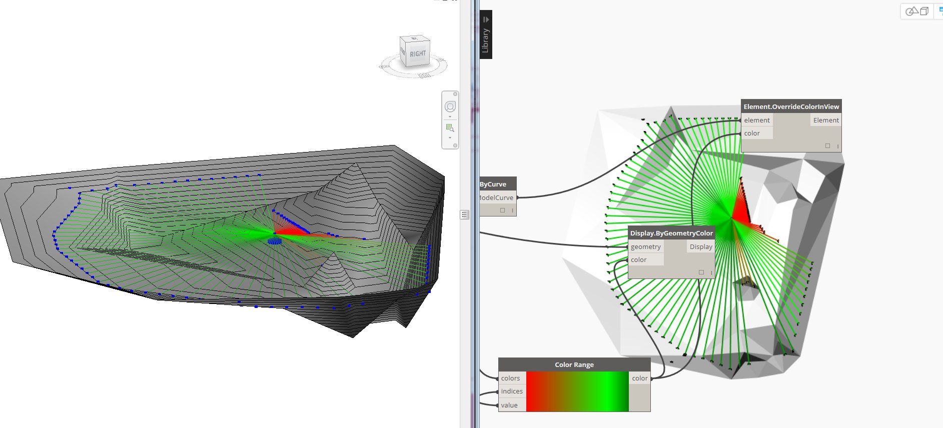
I've been inspired lately by raytracing and what you can use it for in an Revit/Dynamo environment. The inspiration came from Twitter and the wonderful expertise the people I follow possess. It started with Dieter Vermeulens tweet and blogpost here. From there I tested a quick example by using some of the same logic in a topography environment in Revit, ended up looking like this:

(Just to let you know, the raytracing functionality in revit can't do topos, but it can use family instances generated with spring nodes. Hint hint..)
Anyway, I shared the above pic on Twitter and it got retweeted by, among others, "some guy" called Amar Hanspal. I may have to study the Autodesk Organization Chart a little better, because it was Dieter who had to point out that it was Autodesk' very own Product SVP . Holy cow.. Thanks!
Now another helpful guy called Dimitar Venkov, pointed me in direction of another wise gentleman called Kean Walmsley and his blogpost here.
Reading this post I got to know what isovists are, and naturally wanted to explore this a bit more.
From Wikipedia: "A single isovist is the volume of space visible from a given point in space, together with a specification of the location of that point."
and a more graphical explanation of a 2d isovist because we are so visually oriented..


Dieter confided to rooms and I thought why not go outside that window and into the cityscape? In a preliminary design phase it would be nice to have some sort of analysis of what you actually see from the 73th floor balcony in your building wouldn't it?
So how do we get about this then? Well, the guys behind the acoustamo package have pointed out that the raytracing in Revit is a bottleneck. But I think it has worked pretty well so far. Another simplification I've made is that I have enclosed the entire test area with a circular wall that I've hidden in all but one view
Overview:
Raytracing and filtering:
(There are many way to produce the vectors which are fed into the RayBounce node, but i used spherical coordinates as it is applicable to 3d isovists as well.)
As this is more of a proof of concept I've included some different result presentations as examples. Let's hope some real architects come up with something better. (They're probably using grasshopper/rhino anyways, but still..)
Results from the various parts:
Regular detaillines:
Model curves overridden by color by lengths:
Model curves by perimeter:
Detail region created from the above model curves:
Results from the various parts:
Model curves overridden by color by lengths:
Visualisation in dynamo:
Detail region created from the above model curves:
Direct shape by perimeter:
Now, there are many things you can use this for and the pics above are but a few examples. Still, the power of Dynamo is that it makes us able to create tools where WE can decide what the outcome will be by ourselves.
Now if I only can figure out a way to create a 3d Isovist solid..


THANK YOU FOR THE INFORMATION
SvarSlettPLEASE VISIT US
autocad drafting in UK